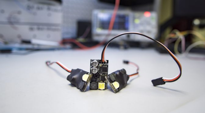
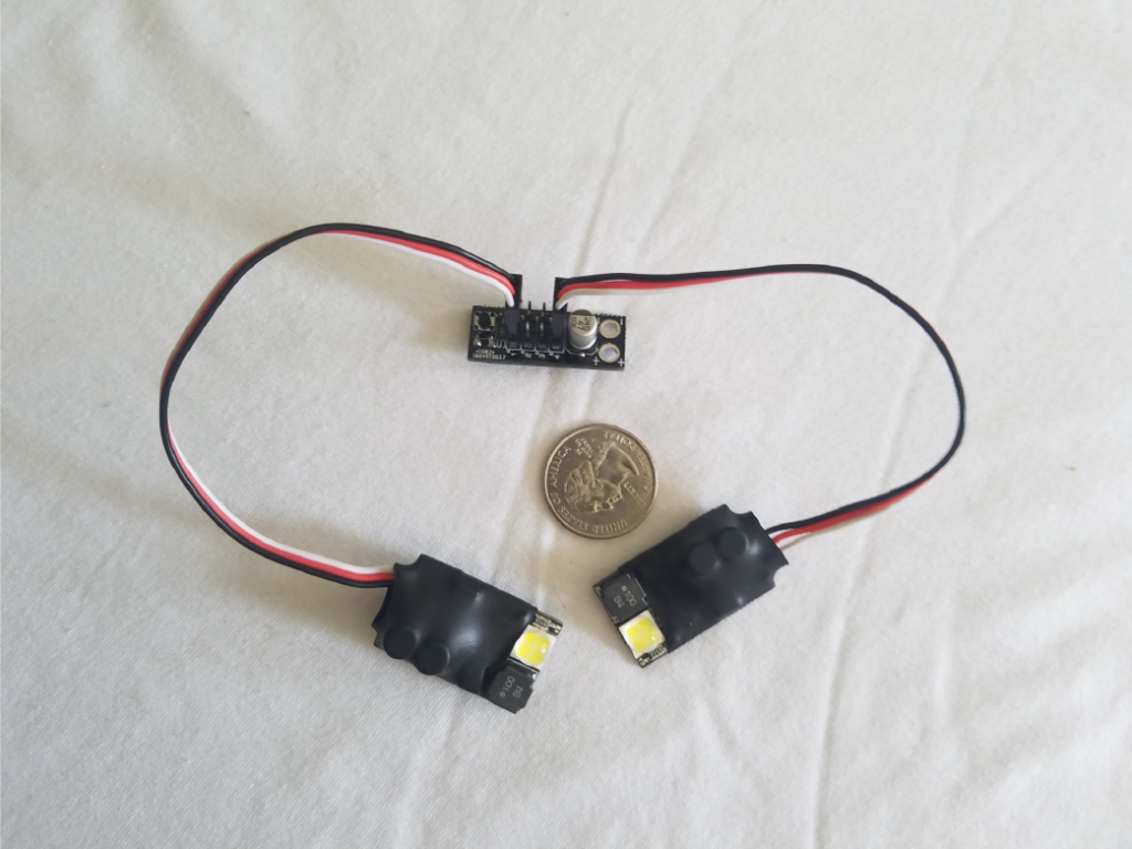
This high-power LED board is lightweight and tiny, a perfect fit for RC planes and quadcopters for extreme visibility during dusk/nighttime flights. We’ve tested visibility out to 5 miles in darkness, and it can be spotted very easily from that distance.
A CREE LED outputs around 2300 lumens of 6500K brilliant white light, making it very easy to spot in the air. A microcontroller onboard controls the LED driver and blink pattern, synchronizing with up to 7 other SyncLights on the same signal bus! This module accepts a wide voltage range, give it anywhere between 10-42V and you’re good to go!
Here is a video showcasing how bright these are… the left SyncLight is running at 40% brightness:
An optional ‘mode-change board’ allows the user to power 4 or 8 boards from one supply, and change blink pattern with the press of a button. The boards come default set to the Master Strobe pattern. We also have a specialized breakout board for the 3DR Solo which has four SyncLight connectors. See ‘Options’ below.
You can choose from 10 different blink patterns to make all your SyncLights work together to create your perfect navigation pattern (each cycle is around 2 seconds long). The SyncLights ‘remember’ the selected blink pattern through reboots. Also included is an ‘Off’ setting, which allows you to work on your RC aircraft with the SyncLights turned off without having to unplug them:
- Hold down the pattern-change button for 3-4 seconds until the SyncLight blinks dimly. Once released, the SyncLights will turn off their output until power cycled. This is good for temporarily suppressing the SyncLight output, without worrying about turning them on next time you go fly.
- Hold down the pattern-change button for 6-7 seconds until the SyncLight double-blinks dimly. Once released, the SyncLights will suppress their output, even after power cycled. This is good if you need to power-cycle your RC aircraft a few times while working on it.
In either case, after the SyncLights have been suppressed, press the button once more to return to the previously selected blink pattern.
Patterns
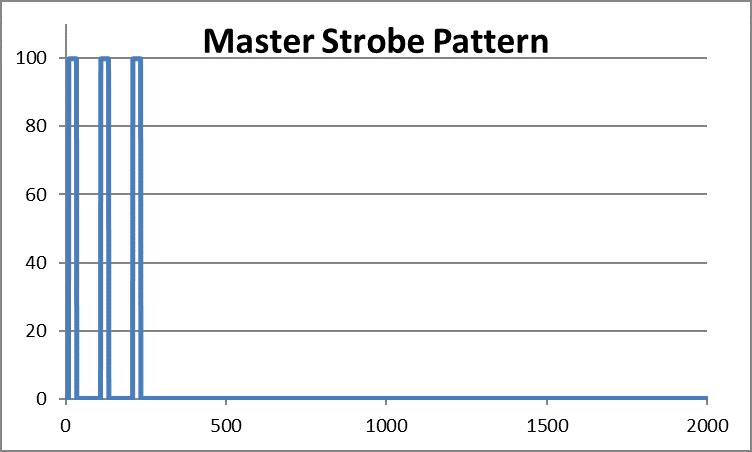
The patterns you can choose from are as follows (the graphs are for visual reference only, and may not be accurate to the millisecond):
- Master Strobe (3x 25ms flashes, spaced 100ms apart, beginning at time t):
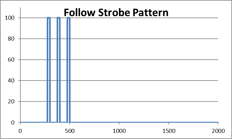
- Follow Strobe (3x 25ms flashes, spaced 100ms apart, that begins at t+0.3s):
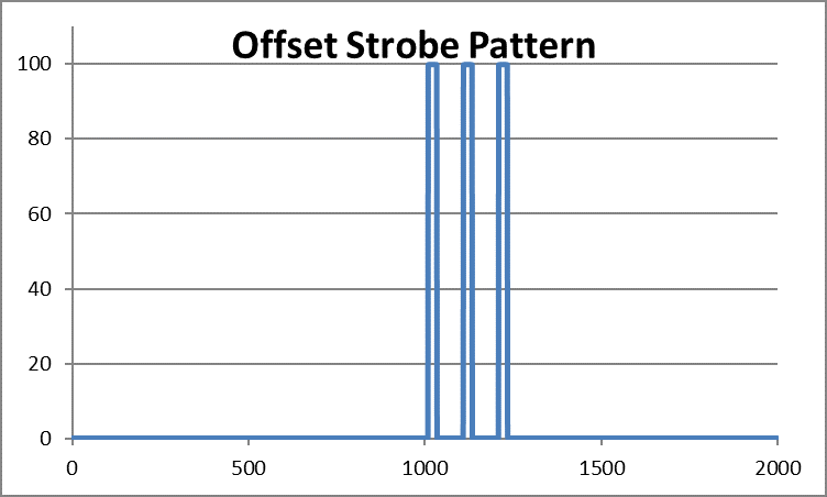
- Offset Strobe (3x 25ms flashes, spaced 100ms apart, that begins at t+1s):
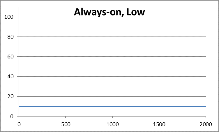
- Always on, 10% brightness:
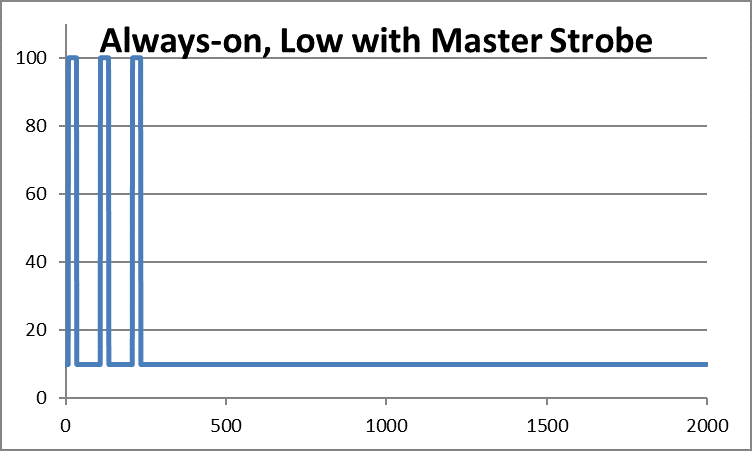
- Always on, 10% brightness w/ Master Strobe overlaid:
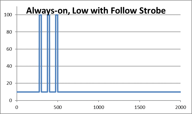
- Always on, 10% brightness w/ Follow Strobe overlaid:
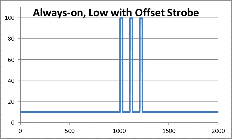
- Always on, 10% brightness w/ Offset Strobe overlaid:
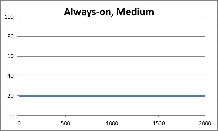
- Always on, 20% brightness:
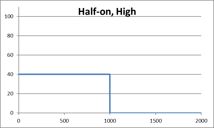
- Half-on (40% brightness, starting at time t, ending at time t+1s):
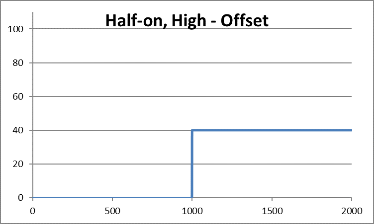
- Half-on Offset (40% brightness, starting at time t+1s, ending at t+2s):
Some common pattern combinations include:
- “Master Strobe” on both wings, with “Follow Strobe” on the tail. This gives a very standard-looking aviation light pattern.
- “Master Strobe” on one wing, “Offset Strobe” on the second wing.
- “Half-on” under one wing, and “Half-on Offset” on a second gives wig-wag landing lights.
Since the SyncLight’s blink pattern is saved onboard the SyncLight, and the pattern change button affects ALL SyncLights on the signal bus, we recommend setting each SyncLight to the desired pattern individually before connecting them all together. For example, if you have SyncLight 1 on the ‘Master Strobe’ and SyncLight 2 on the ‘Follow Strobe’, when you press the pattern change button, SyncLight 1 will change to ‘Follow Strobe’ and SyncLight 2 will change to ‘Offset Strobe’.
Important considerations:
Power:
The boards are designed to accept an input voltage anywhere between 10-42V (3S to 10S). While the input connector is a standard ‘servo’ style, it will not work on standard servo voltages. The pinout is the same: Black for ground, Red for 10-42V, and White for the signal bus. Take care not to plug the SyncLight into your system incorrectly: while there are protections built-in to mitigate most mis-wirings, the protections cannot prevent damage from reverse voltage, and the SyncLight will be permanently damaged.
Do not hot-plug one SyncLight into an already-powered SyncLight group. The voltage fluctuations caused may trigger a ‘pattern change’ event on the already-powered SyncLights, and lead to undesirable operation. Make sure the system is powered off before adding an additional SyncLight to the bus.
The LED is driven at 6-6.2V at 3A, so a nominal 18W draw is expected when the LED is on fully. When the LED is PWMed, the apparent current draw is reduced. A table is provided with amperage measurements taken at 16.8V (4S):
| LED Mode | Amperage @ 16.8V |
| Always-on Low | 0.15A |
| Always-on Medium | 0.28A |
| Half-on, High | 0.53A (When ‘On’) |
| Strobe | 1.2A (Momentary) |
Heat:
The board will get warm/hot to the touch if you use any mode other than “Master Strobe”, “Follow Strobe”, or “Offset Strobe” with no airflow, no heatsink, and no other form of cooling. The boards will not damage themselves, but ensure your mounting method can withstand the heat if you choose one of these modes.
For example, if used in a room-temperature environment with zero airflow, a SyncLight running the “Always-on, Low” pattern (with or without strobes) will stabilize around 70°C without a heatsink, or 50°C with a heatsink.
A SyncLight on the “Half-on” or “Always-on, Medium” modes will stabilize around 110°C without a heatsink, and 60°C with a heatsink (again, if used in a room-temperature environment with zero airflow)
Adding airflow (such as from the propellers of your drone) will reduce these temperatures radically.
Mounting:
Mounting methods include (but are not limited to):
- Hot glue – If using the “Master”, “Follow”, or “Offset” strobe patterns, the SyncLight will stay cool enough to allow it to be mounted using hot glue without it melting. We cannot guarantee that a SyncLight running any other mode will not melt hot glue if you choose to use it as a mounting method.
- Machine screw – If a more robust mounting method is desired, removal of the heat shrink around the SyncLight will reveal a center hole which accommodates a screw size of #6-32.
- Mushroom Hook Velcro
- Zip Ties – If you’re mounting this to an arm of a drone, a simple zip tie around the center of the SyncLight will suffice.
Options:
- Heatsink kit. For installations with limited airflow, or if improved thermal dissipation is otherwise necessary for your application.
- Four-way mode change board. Allows up to four SyncLights to share the same power source, and to synchronize patterns to each other. Allows user selection of blink pattern.
- Eight-way mode change board. Allows up to eight SyncLights to be powered from the same source. An included jumper allows all eight boards to synchronize, or to have two independent banks of four SyncLights to synchronize. Allows user selection of blink pattern.
- Solo Synckit. Connects two SyncLights to your 3DR Solo multirotor with ease. This kit consists of two SyncLights, a breakout board with necessary connections broken out, and breakout board mounting hardware.
Advanced:
For the developers, this board is fairly simple to reprogram. The necessary pins for connecting to the AVR microcontroller (ATtiny85) are exposed as small pads on the bottom of the SyncLight. The LED driver turns on the LED when the EN pin (connected to the tiny85 pin 6) goes high. The signal input pin on the SyncLight is connected to the tiny85 pin 2. Happy hacking!
Leave a Reply